
Power cable monitoring solutions
Power Cable and Substation monitoring
Power Cable and Substation monitoring
Regardless of the cause, fire accidents involving power cables go through the following stages: insulation damage at a certain point of the cable → intermittent or continuous discharge → significant decrease in insulation and localized heating → explosion or arc occurrence at a specific point of the cable, resulting in the generation of harmful gases → fire spreading throughout the cable tray and cable trench.
Characteristics of cable fires:
Rapid and intense spread: Power cables themselves are highly flammable. As the number of cables inside cable tunnels increases and dense installations are adopted, with some even overlapping or intersecting with high-temperature pipelines, the cable interlayers are filled with a network-like arrangement of cables. Additionally, the height difference in cable shafts creates natural airflow, and the affected cables cannot be immediately de-energized in the event of a fault or fire. Therefore, once a fire starts in these areas, it becomes extremely fierce and poses significant hazards.
Difficult repair: Cable fires generate a large amount of smoke and toxic gases, with high levels of CO and CO2. In particular, ordinary plastic cables are not only prone to ignition but also produce hydrogen chloride gas, which can diffuse into electrical equipment rooms through gaps and holes. This forms a corrosive layer of salt on the equipment, greatly reducing insulation in the devices and wiring circuits. Even after the fire is extinguished, safety operations are still affected. This is known as secondary hazard.
Chemical plants, power plants, and other large industrial enterprises have a substantial amount of power cables and control cables installed, connecting various high-voltage equipment. These cables are distributed within cable shafts, cable tunnels, cable trays, and cable interlayers.
Cable fire accidents account for approximately 15.6% of industrial fire incidents, with around 25% caused by cable faults themselves or external factors.
Since most fire accidents are caused by excessive temperatures, it is crucial to monitor cable temperature changes accurately and issue timely warnings before a fire occurs. This provides users with sufficient time to take appropriate measures and prevent accidents or fires.
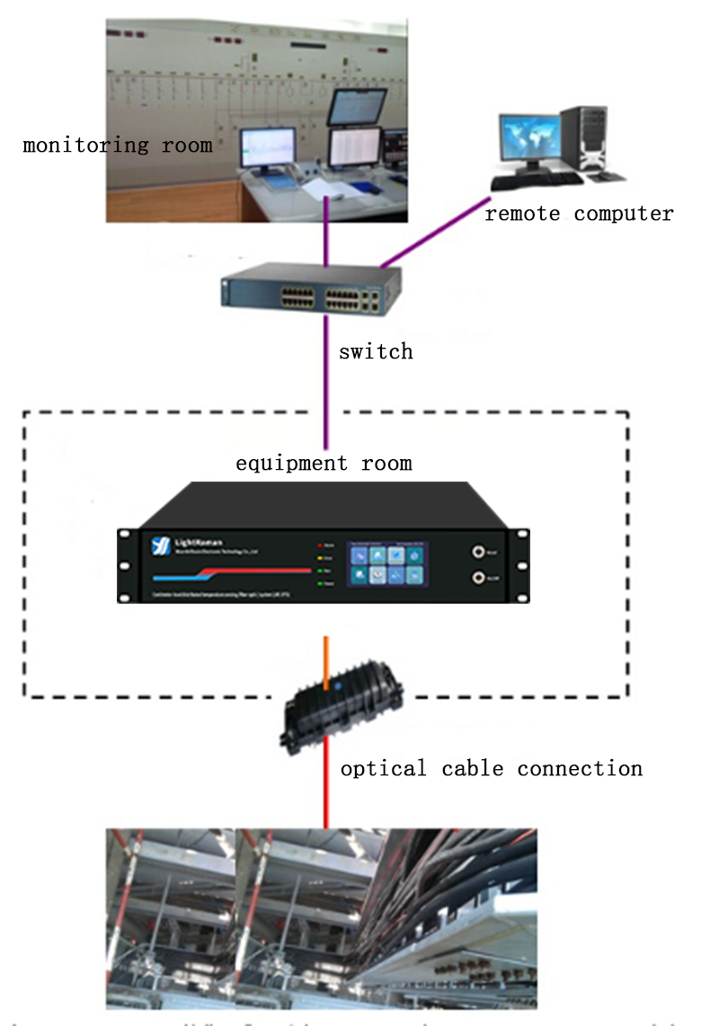
By using a 4km, 8-channel distributed temperature sensing (DTS) system, real-time temperature measurements at any location on the cable trays of chemical industrial substations can be achieved, emphasizing a proactive approach to prevention. Once the measured environmental temperature value or temperature rise rate on the cable trays exceeds the set threshold, the system automatically triggers an alarm and sends real-time alarm signals to the control room via Ethernet or relays, facilitating the response of on-duty personnel.
The measurement unit is placed in the control room, and the distributed temperature sensing system can be connected to the control room through routers or network cables. It is used to display temperature distribution curves, visual interfaces, and alarm information. The main functions include instrument parameter settings and management, as well as displaying temperature and alarm information. The user-end software is installed on the user's PC, allowing remote access to real-time temperature data and alarm information.
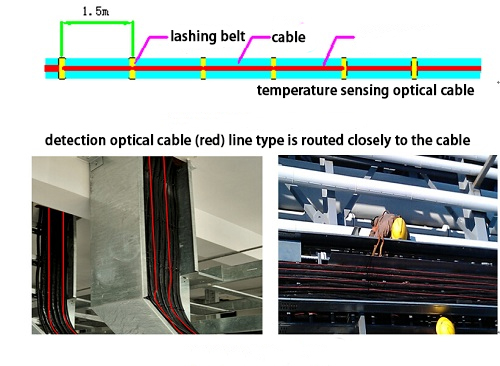
The detection optical fiber is fusion spliced with a tail fiber, and the fusion splicing section is protected by an optical fiber splice box. The detection optical fiber is led out from the measurement unit and laid closely along the cable tray in line with the cable shape. Plastic zip ties can be used to securely fasten the detection optical fiber to the cable at critical locations.
Installation method of detection optical fiber:
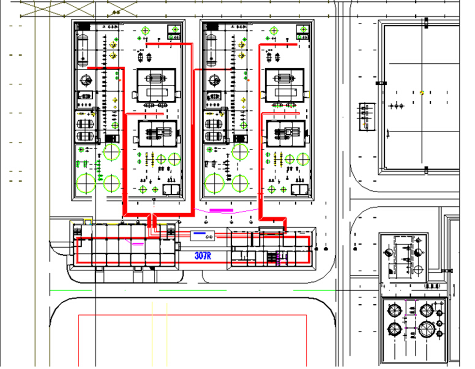
Each detection optical fiber is connected to the DTS measurement unit via a tail fiber. One end of the tail fiber is connected to the measurement unit, while the other end is fusion spliced with the detection optical fiber through a splice box. This solution adopts a 4km, 8-channel DTS system, and the routing of the cable tray is divided into separate channels as shown in the diagram, with reserved channels for backup purposes or for monitoring other areas such as oil storage rooms.
To enhance the response to cable hotspots, multiple detection optical fibers are linearly buried in the cable tray. Each cable tray has four detection optical fibers running back and forth to better capture temperature information.


