
Power cable monitoring solutions
Shougang Flue Gas Desulfurization Project: Cable and Switchgear Fiber Optic Temperature Monitoring System
Shougang Flue Gas Desulfurization Project: Cable and Switchgear Fiber Optic Temperature Monitoring System
Chemical plants, power plants, and other large industrial enterprises have a large number of power cables and control cables, which are connected to various high-voltage equipment. These cables are distributed within cable shafts, cable tunnels, cable trays, and cable interlayers.
Cable fires account for 15.6% of industrial fire accidents, with approximately 25% caused by cable faults themselves and the remaining caused by external factors. Most fire accidents are due to excessive temperatures. Therefore, timely and accurate monitoring of cable temperature changes and issuing warnings before a fire occurs is crucial, as it provides users with sufficient time to take appropriate measures and prevent accidents or fires.
Cable and switchgear fires have the following causes and characteristics:
According to statistical analysis, there are two main categories of causes for cable trench, cable tray, and tunnel fires:
(1) Internal causes: Fires caused by cable faults themselves. There are many reasons for cable faults, including
:a) Quality issues with cable products;
b) Aging of cables due to long operation time;
c) Long-term operation of cables under overload or harsh environmental conditions;
d) Low construction quality or poor joint manufacturing processes for cables;
e) Deliberate damage to cables.
(2) External causes: Flammable gases (such as coal gas, natural gas, biogas, etc.) entering cable trenches or tunnels. Due to the relatively closed nature of cable trenches and tunnels, when exposed to open flames (caused by human activities or cable discharge), the entire cable segment can immediately explode and catch fire.
Distributed Temperature Sensing (DTS) is an advanced international temperature measurement technology that enables distributed temperature measurement of the entire cable tray and cable trench. It can promptly detect cable overheating spots and prevent "ignition," which is of great significance for ensuring the safe operation of large-scale industrial and mining enterprises.
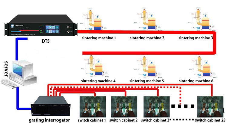
This project uses one DTS fiber optic temperature sensing system and one fiber optic grating temperature demodulator to achieve real-time temperature measurement in any position of six sintering machine cable trenches and temperature monitoring of key positions in 23 high and low voltage switchgear cabinets, focusing on preventive measures. Once the measured temperature values or temperature rise rates exceed the set threshold, the system will automatically alarm and send real-time alarm signals to the control room via Ethernet or relays, facilitating the actions of on-duty personnel.
The measurement host is placed in the control room and contains a high-performance embedded industrial computer with temperature measurement system server software installed. The measurement host is connected to a VGA interface LCD display for showing temperature distribution curves, switchgear visualization interfaces, and alarm information.
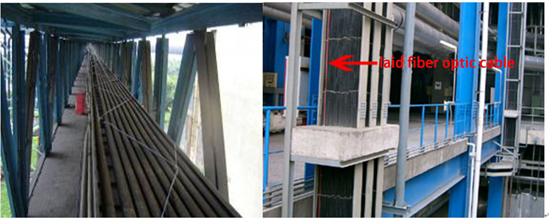
The detection fiber optic cable is fusion spliced with a tail fiber, and the fusion splice is protected within the cable junction box. The detection fiber optic cable is led out from the measurement host and closely laid along the cable lines or sinusoidal waveforms. Plastic zip ties can be used to fix the detection fiber optic cable to the cables at critical locations. Fiber optic grating sensors are installed at key positions in each switchgear cabinet.
This project uses a distributed fiber optic sensing system to measure the temperature of cables in cable trenches and uses the fiber optic grating demodulator to measure key areas in switchgear cabinets. The data from both sources are integrated and uploaded to the server for information aggregation, ultimately forming an integrated monitoring system for cable trenches and switchgear cabinets.
Each detection fiber optic cable is connected to the DTS measurement host via a tail fiber (provided with the host during supply), with one end of the tail fiber connected to the measurement host and the other end fusion spliced to the detection fiber optic cable via a splice box.
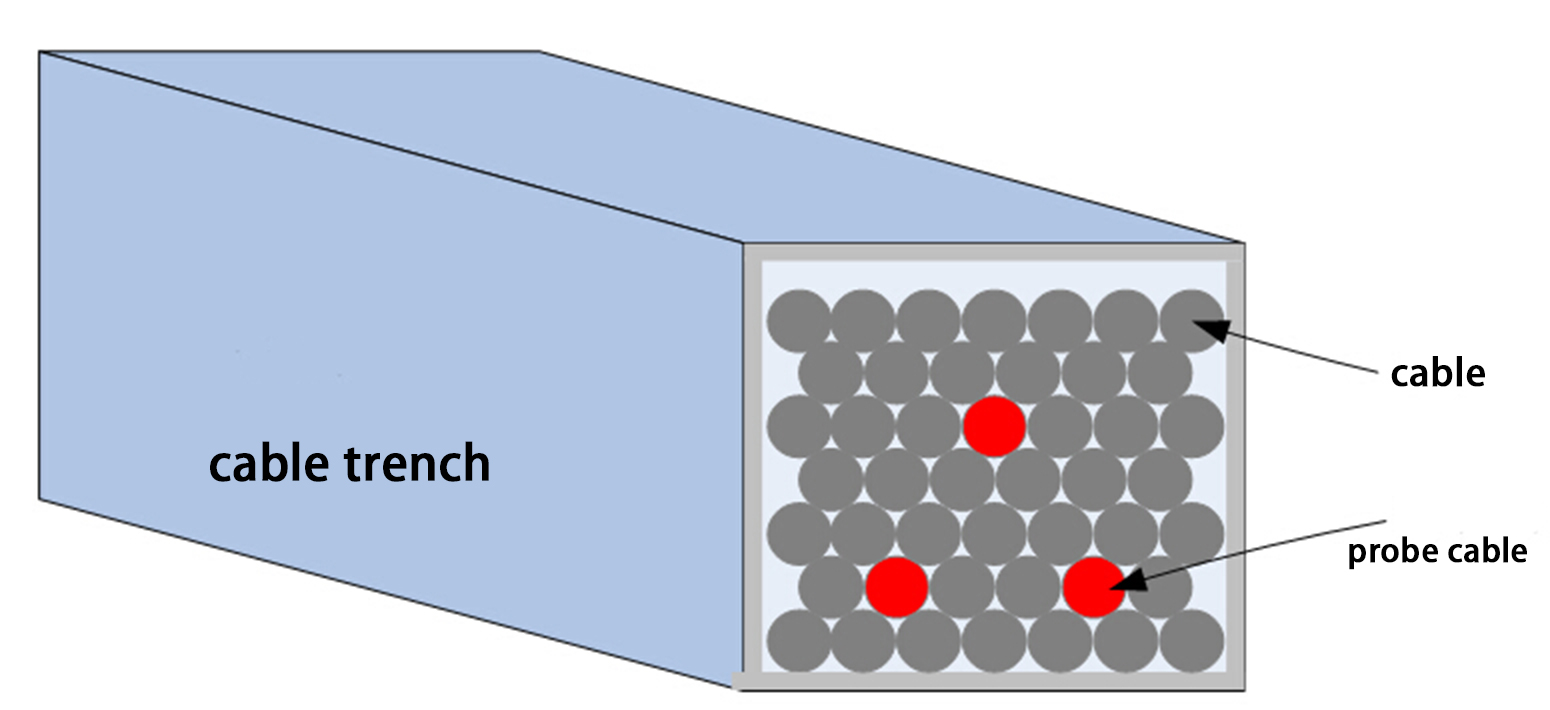
For cable trenches, the detection fiber optic cable is typically laid along the cable lines or in a sinusoidal waveform. In this project, multiple detection fiber optic cables (linearly laid) are buried in the cable trough to enhance the response to cable hotspots. Additionally, the cables can be laid in a sinusoidal shape on the upper surface of the cables.


